
If you saw early i hit a snag getting the crank in
/4g15-bottom-end-main-stud-install-arp.html
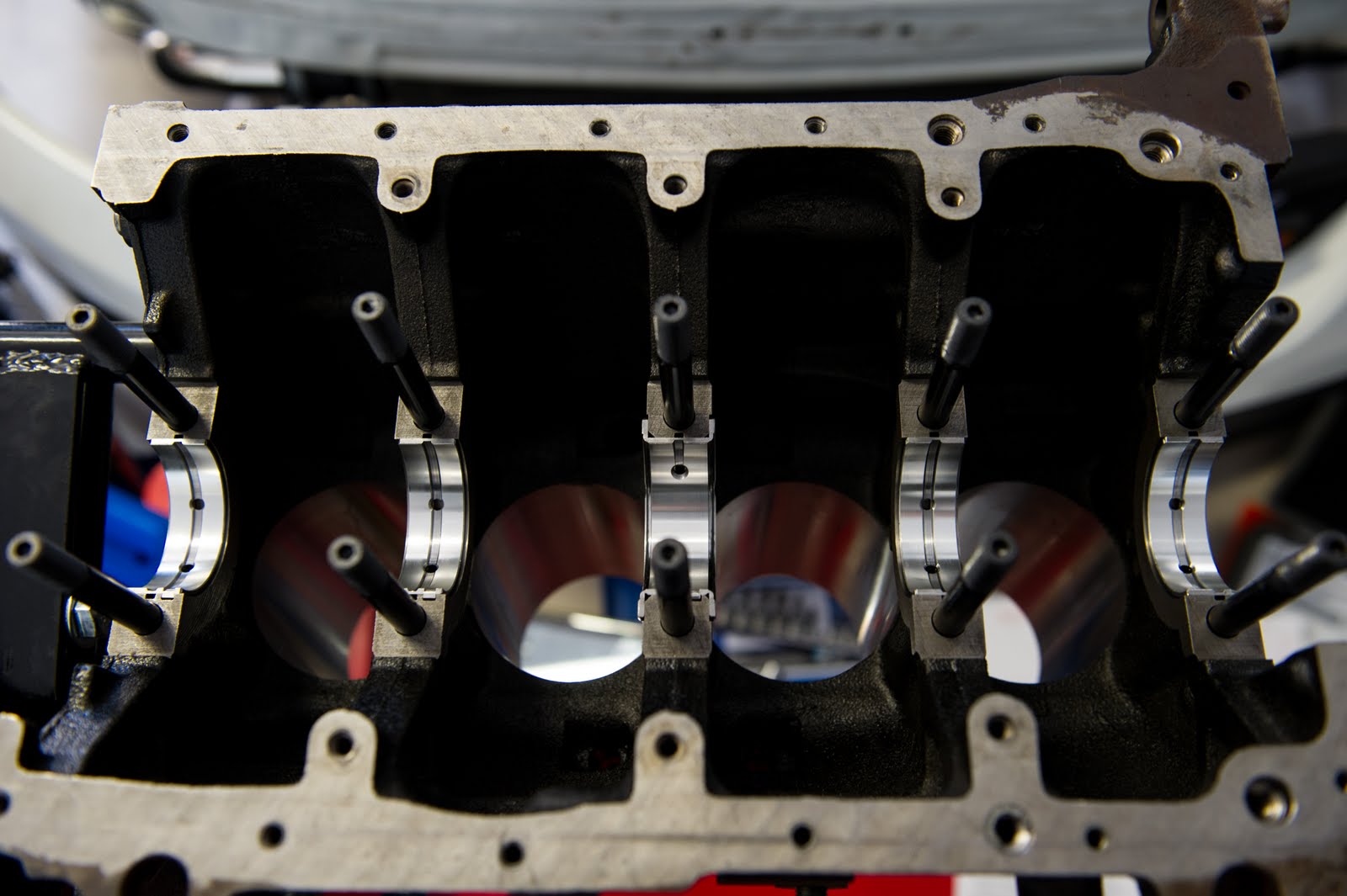
I managed to get the crank in today (day two of the build). I stripped all the studs out, thread chased the block again and cleaned all surfaces.
I installed the studs, torqued down the main caps and measured all the main journals.
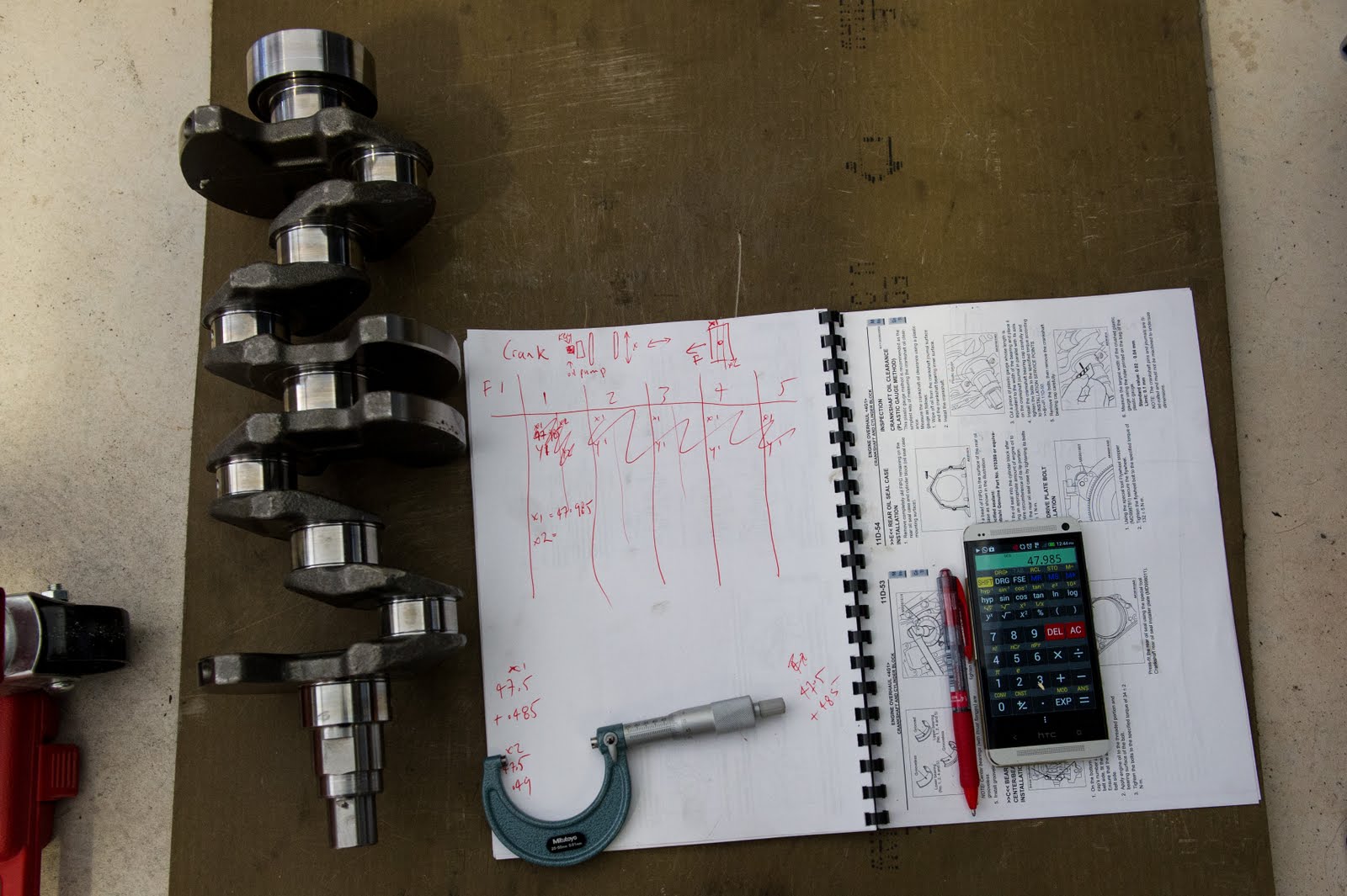
Part of the process i go through is zero all instruments before i begin. A vice comes in handy when holding the micrometer and using it to set a dial bore gauge.

Measuring main journals.


I was using telescopic gauges but i found they weren't reliable and giving a fair amount of difference in results. I believe it could be due to the face that i was using it outside of its comfort range.
They are max 54mm and i am trying to measure 52mm.

I setup the dial bore gauge with a 50mm tip and a 3mm spacer.

Install grooved bearings to the cylinder block.
NOTE: Center bearings (with thrust flanges) are
grooveless.
Install grooveless bearings to the bearing caps.

After fitting the bearing caps, measure the end
play in the crankshaft. If the measurement
exceeds the specified limit, replace the crankshaft
bearings.
Standard value: 0.05 − 0.18 mm
Limit: 0.25 mm
On the bottom surface of each bearing cap is the
capís number and an arrow. Starting at the timing
belt side, fit the bearing caps in numerical order.
Ensure that the arrows point toward the timing
belt side.

This plastic gauge method is recommended as the simplest way of measuring the crankshaft oil clear-ance. Measure the crankshaft oil clearance using a plastic gauge as follows:
1. Wipe off oil from the crankshaft journal surface and the crankshaft bearing inner surface.
2. Install the crankshaft.

3. Cut a piece of plastic gauge whose length is
equivalent to the width of the bearing and place it on the crankshaft journal in parallel with its axis.
4. Install the crankshaft bearing cap carefully and tighten the bolts to the specified torque according

5. Remove the bolts, then remove the crankshaft bearing cap carefully.
6. Measure the largest width of the crushed plastic gauge using the ruler printed on the bag of the plastic gauge.
Standard value: 0.02 − 0.04 mm
Limit: 0.1 mm

NOTE: The crankshaft pins and journals are fillet-rolled and must not be machined to undersize dimensions.

I measured all the crank journals. Both x and y axis and also left and right of the oil feed.
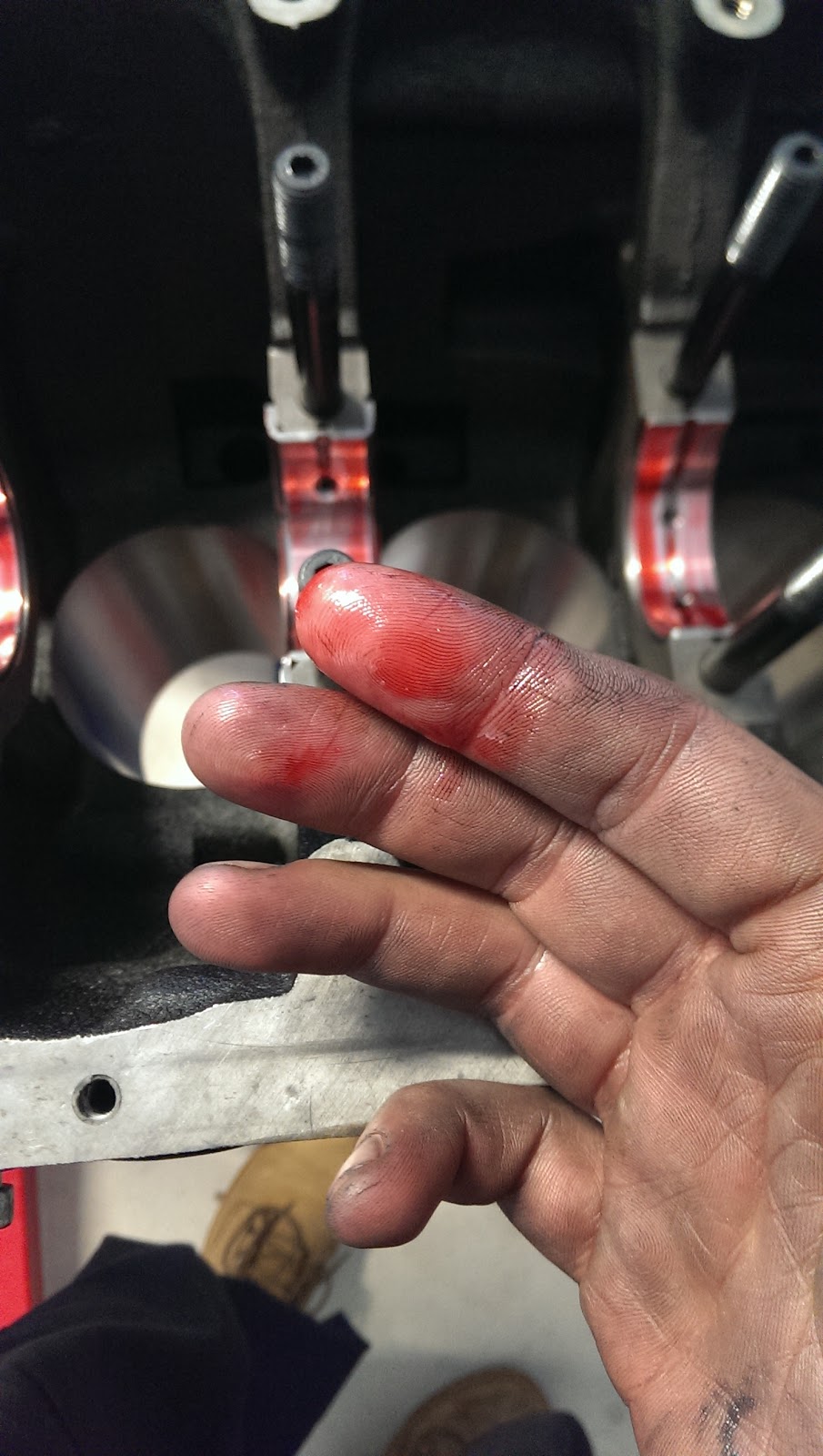
Removed the main caps and installed the bearings with plasti gauge.
I had calculated the oil clearances already. I will post them up late. But i was looking for a .02-.04mm oil clearance.


I wanted to accomplish something hence i went ahead and installed the crank. It might have to come out again, i am not sure. I hope not.

CRANKSHAFT AND CYLINDER BLOCK (LIMIT)
Crankshaft end play mm 0.05 − 0.18 (0.25)
Oil clearance at crankshaft journals mm 0.02 − 0.04 (0.1)
Cylinder block gasket surface warp mm 0.05 (0.1)
Cylinder block gasket surface grinding limit
(including cylinder head grinding amount) mm − (0.2)
Cylinder bore diameter mm 75.50 − 75.53 (−)
Taper of cylinder mm 0.01 or less (−)
Cylinder-to-piston clearance mm 0.02 − 0.04 (−)

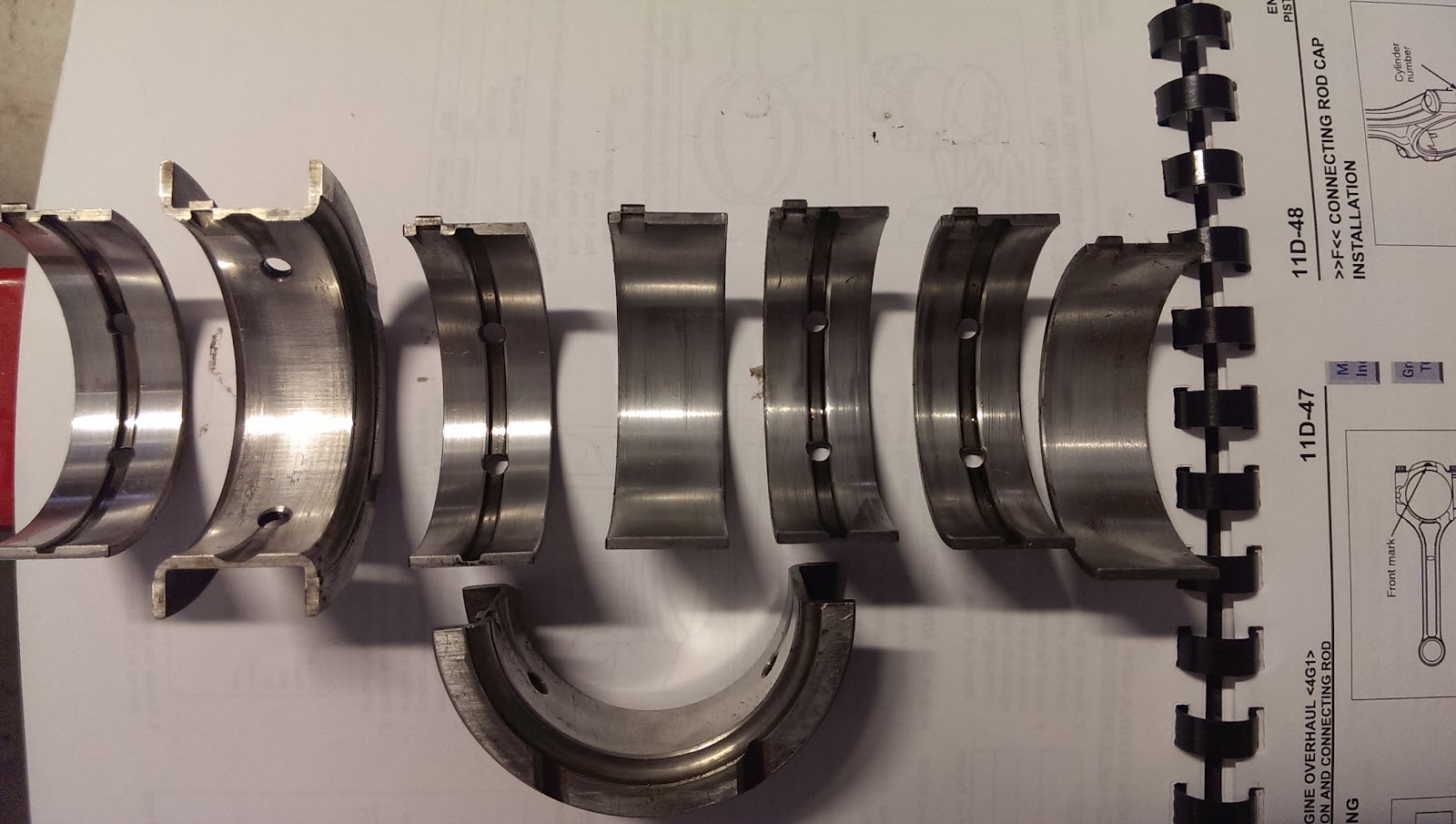
OEM Bearings - unusual wear i think


ATM i am thinking of crocus cloth vs emery cloth to just remove any high spots.
Block Markings were 11111 (hence no1 to no5 all came in the same)
Journal diameter mm 47.988 − 47.994
Bearing identification mark 3
Crank Markings 22222
ABBB1
Working out sizes /selecting-bearing-piston-sizes-for.html
See more about the bent rod here /bent-rod-z27ag-4g15-more-to-come.html
Bearing picklist /rcolt-rebuild-pick-list-part-numbers.html
 Assembly specs /z27a-4g15-engine-re-assembly-torque.html
--- A ding i saw in the crank. Makes me wonder if it was polished @_@
WISECO PISTONS SPECS
Suggest Clearance on Piston Kit Spec sheet is 0.0035 (0.08889999999999999mm)
Spec sheet 1: Bore 2.9920" = 75.9968mm (.5mm oversized)
Spec sheet 2: Bore 3.0120" = 76.5048mm (1mm oversized)

CYLINDER BLOCK
1. Visually check the cylinder block for scratches, rust, and any other corrosion. Also check it for cracks using a flaw detecting penetrant. If any defect is evident, replace the cylinder block.
2. Use a straightedge and thickness gauge to check the cylinder block top surface for warp. If the warp exceeds the specified limit, correct by grinding.
Make sure that the surface is free from remaining gasket material and other foreign matter.
Standard value: 0.05 mm
Limit: 0.1 mm
Grinding limit: 0.2 mm
3. Check cylinder walls for scratches and seizure. If defects are evident, rebore to oversize or replace the cylinder block.
4. Use a cylinder gauge to measure the cylinder bore diameter and taper. If the cylinder is worn badly, rebore it to an oversize and replace the piston and piston rings with ones matched with the new bore size. The points at which the measurements should be made are indicated in the illustration.
Standard value: 75.50 − 75.53 mm
Taper: 0.01 mm or less
BORING CYLINDERS
1. Select an oversize of the pistons to be used based on the largest of the cylinder bores.
2. Oversize pistons are available in two oversizes 0.50 mm and 1.00 mm. Bore each cylinder to a size that provides the standard clearance when combined with the selected piston. The reference position for piston diameter measurement is as shown in the illustration.
3. Based on the piston diameter measurement, calculate the boring finish dimension.
• Boring finish dimension = [Piston diameter] + [0.02 − 0.04 mm (clearance between piston an cylinder)] − [0.02 mm (honing margin)]
CAUTION
To prevent deformation of cylinder block that would result from the heat generated by boring bore the cylinders in the following sequence:
No. 2 → No. 4 → No. 1 → No. 3.
4. Bore all the cylinders to the calculated boring finish dimension.
5. Hone the bored cylinders to the final finish dimension (piston diameter + clearance between piston and cylinder).
6. Check the clearance between the piston and cylinder.
Standard value: 0.02 − 0.04 mm
hey man, very nice work. Can you help me with the part code for the ARP main stud kit and the head studs?
ReplyDelete